6.5 Lab Exercise: Digital Electronics and the Blinker Circuit
The objectives of this lab exercise are for students:
- To be introduced to digital circuits
- To understand the 555 timer
- To learn to solder
- To analyze and build relatively complex circuits
Materials
The following materials are required for each lab station:
- A PC with LabVIEW installed
- A myRIO configured with LabVIEW
- A multimeter
- A breadboard
- A prototyping board
- Wire and jumper wires
- A 9 V battery
- A 9 V battery connector
- A 555 timer integrated circuit
- Two 1 kΩ resistors
- A 470 kΩ resistor
- An LED
- A 1, a 10, and a 100 μF capacitor
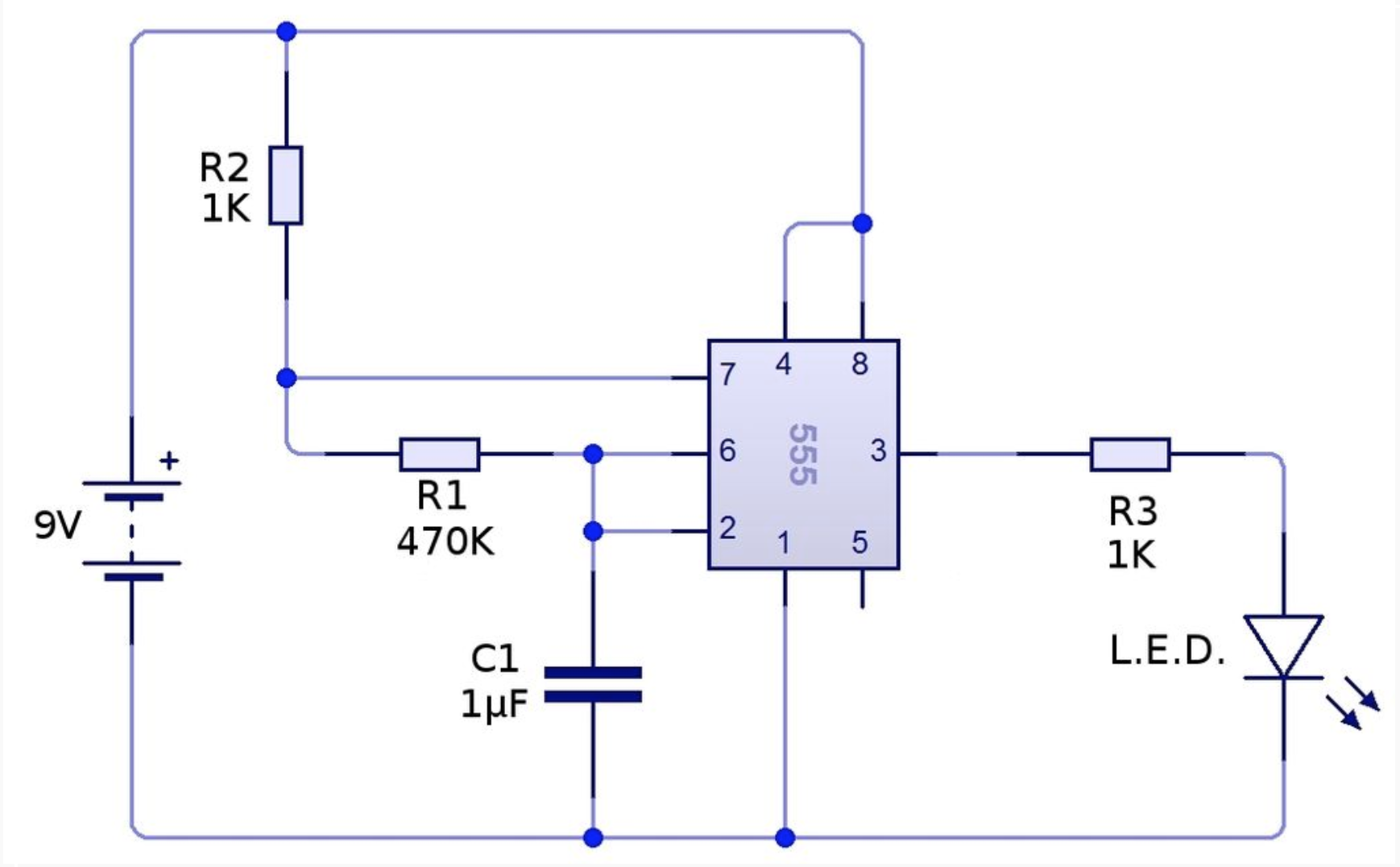
Building the circuit
Use the following procedure to build the LED 555 timer circuit.
- Gather the components listed above.
- Measure and record the parameter value for each resistor, each capacitor, the battery, and the LED in the table below.
- Lay out the circuit in accordance with the circuit diagram of figure 1 on a prototyping board. Use the 1 μF capacitor, but connect it with an auxiliary breadboard.
- Leaving the battery disconnected from its connector, solder each connection, connecting components that aren't directly next to each other with wires.

Component Measurements
Measuring the waveform
The LabVIEW VI needed for this lab exercise can be downloaded here:
Use the myRIO with the LabVIEW VI, which is similar to those we've used previously, to record at least a few periods of \(v_{C_1}\) and \(v_{R_3}\).
Repeat the previous step with the 10 μF capacitor and the 100 μF capacitor. Be sure to capture several periods of data for each circuit.
Report requirements
Write a report on your laboratory activities using the template given. Be sure to pay special attention to the following elements:
- In your circuit analysis, predict the entirety of the capacitor voltage waveform for each circuit (different circuits here meaning different capacitors).
- Plot your prediction and the measured waveforms on the same graph (one graph for each circuit, three in total). One period is sufficient, but multiple is also fine. A bit better would be to average multiple periods of measured data. However, some difficulty arises when trying to match the period and this is not required.
It may be helpful to take photos during the laboratory procedure. These can be included in your report.
Portions of this lab exercise were prepared by Ryan Haseman (SMU class of 2017) Jordan Parker (SMU class of 2019).
Bibliography
- Community, Wikipedia. "555 pinout".
- Trilesto. "Flashing LED using 555 timer".