2.3 Circuit Prototyping
When building a circuit for a one-time application or prototype, it’s best to use a temporary construction method.
Production circuits are almost always fabricated as printed circuit boards (PCBs), such as the one shown in figure 1. These can be mass-produced cheaply and reliably. In recent years, custom PCB fabrication has become affordable even for low-volume projects, often costing only tens of dollars per board (plus components).

For low-weight but reliable prototypes, soldered wires and components are often used. However, for even earlier stages of design, more flexible construction methods are appropriate.
Breadboards
Breadboards, such as the one shown in figure 2, are plastic boards with embedded metal clips arranged to form standard circuit connections. Components and jumper wires can be inserted into holes to build and test circuits quickly.

Breadboards have:
- Bus strips (or power rails) along the outer edges, often marked with red (+) and blue (−) lines. Each color corresponds to a continuous strip of connected holes.
- Terminal strips in the middle, where columns of five holes are electrically connected. The notch in the center separates left and right sides, allowing integrated circuits (ICs) to be inserted across the gap.
An example circuit is shown in figure 3.

In this example, two resistors share a node at row 40. Power and ground are supplied through the rails. The upper ground rail is bridged to the lower one.
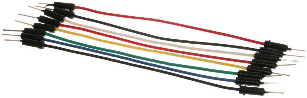
To complete circuits or connect more distant points, we use jumper wires, shown in figure 4.
Coaxial Cables
To connect lab instruments (e.g. function generators or oscilloscopes) to a circuit, we use coaxial cables. These contain a central hot conductor, surrounded by a tubular grounded shield—see figure 5.

Because of this structure, coaxial connections place the instrument in parallel with the circuit.
BNC Connectors
In instrumentation, coaxial cables almost always terminate in BNC connectors, shown in figure 6.

The left image shows a male BNC connector. The middle and right images show female connectors. BNC connectors use a twist-lock mechanism that provides a secure, tactile connection.
The outer barrels of both male and female connectors are tied to ground.
Alligator Clips
To connect coaxial cables to breadboards or bare wires, we often use alligator clips, shown in figure 7.

These clips typically have a red lead for hot and a black lead for ground. They often connect directly to jumper wires.
While convenient, alligator clips are mechanically insecure. Use them only for very temporary prototypes, and never when the circuit will experience movement or acceleration.