6.1 Lab Exercise: Convection
Introduction
One way to characterize the efficiency of a heat exchanger is by comparing the temperature of the extended surface (e.g., a fin) to the base temperature. If the fin temperature is uniform and equal to the base, the fin is considered 100 percent efficient—meaning it is transferring heat as effectively as possible (Bergman, Lavine, and Incropera, 2019, section 3.6). In reality, heat flows along the fin by conduction and escapes to the surrounding air by convection, leading to a temperature gradient along its length. The steeper the gradient, the lower the fin efficiency. In this experiment, we will compare two fin shapes—circular and flat—and evaluate which performs more efficiently under different airflow conditions.
Equipment
The equipment for the experiment includes:
- Armfield Convection Heat Transfer Unit
- NI 9211 data loggers (2)
- PC with LabVIEW software
- Fluke 922 Airflow Meter
- Seven K-type thermocouple probes
- Thermal paste
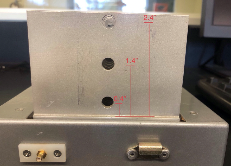
The following figure shows the experimental setup.

Experimental Procedure
- Insert four K-type thermocouples into the holes in the side of the unit so that the ends of the thermocouples are in the middle of the duct. The thermocouples should go in the holes labeled 1, 2, 3, and 7.
- Insert the yellow tube of the air flow meter into the hole in the side of the duct. The black tube can be left in the open as an atmospheric reference.
- Turn the
FANandHEATERpower knobs all the way off (i.e., counter clockwise). - Toggle the main power unit switch to
SUPPLY. - For each of the fin apparatuses (i.e., circular and flat), perform the following steps:
- Insert the fin assembly into the opening on the side of the duct. Clamp it in and plug in the heater cord from the main unit.
- Apply thermal paste to the ends of three additional K-type thermocouples.
- Insert the probes into the holes labeled 4, 5, and 6. Make sure the ends of the probes are in contact with the central fin.
- Zero the air flow meter while the fan is off by holding the
ZERObutton for a few seconds. - Turn the main unit heating power output up to approximately 60 W.
- For each air flow speed (i.e., 0, 1, and 2 m/s), perform the following steps:
- Adjust the fan speed knob to adjust the air flow speed to near the nominal value (i.e., 0, 1, or 2 m/s). Note that for a span speed of 0 m/s, the fan should be left off.
- Open the
Convection.viLabVIEW VI. - Set the time delay between measurements to 3 seconds.
- Start the LabVIEW VI.
- Wait for the system to reach steady state.
- Record the heating power into the system, the measured air velocity, and the steady-state temperatures in the table below. The VI shows a graph and a digital display of the temperature readings.
- Click the
STOPbutton to stop the VI and record the filename of the data file saved in theDocuments/LabVIEW Datadirectory. The files are automatically named with serial numbers.
- Turn down the heater supply power to 0 W.
- If another fin type is to be tested, remove the old fin assembly. Caution: Be careful when removing the fin assembly to avoid touching any hot surface.
- Toggle the main power supply switch away from the
SUPPLYposition.
Lab Report Questions
Within the normal sections of the report, include plots of the time responses and steady-state temperature versus distance from the base plate for the two heat exchangers at the air velocities (nominally 0, 1, and 2 m/s):
- Which heat exchanger shape is more efficient? Why? Is this true for all air speeds?
- Compare the free convection situation (i.e., no forced air) to the forced convection situation.
- Comment on any error or uncertainties that occurred in this experiment.
Equipment Details
Here are some details about the equipment used in this experiment:
- Temperature probes are inserted into the side of the duct to measure air and fin temperatures.
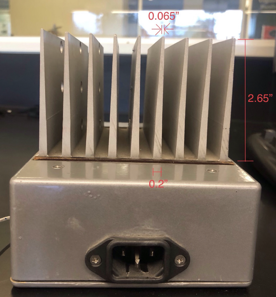
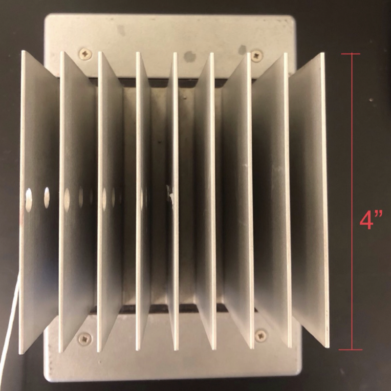
- The flat fins have a small taper from base to tip, and thermocouples are inserted through holes in the fins.
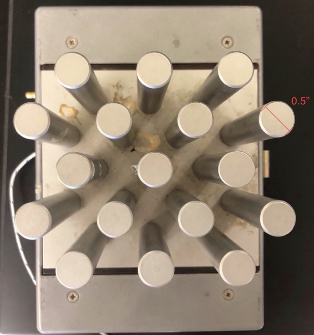
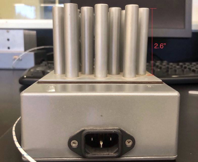
- The circular pins have uniform cross sections, and thermocouples are inserted in a similar fashion.
The figures below show the geometry of the heat exchangers used in this experiment.
Bibliography
- [BLI] Bergman, T. L., Adrienne Lavine, and Frank P. Incropera. Fundamentals of Heat and Mass Transfer. John Wiley & Sons, Inc..